N54 · center-section engineering
TD03 vs TD04
center sections
Twenty-five pounds of boost tells you almost nothing about how hard a turbo is working. It doesn’t say what RPM you were at, how much air was actually moving, or what the shaft, bearings and thrust collar inside that center housing were doing to hold it there. This article opens up the center section and shows what physically changes between a factory TD03 and a TD04-family CHRA — and why the badge on the box is the least useful spec on it.
Reviewed by Justin, Owner & BMW calibration specialist · Synergy BMW Tuning · Updated September 2026
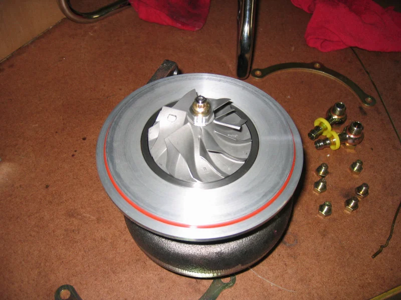 Compressor wheelOil-line fittings
A Garrett GT30 CHRA, used here as a real-hardware reference for scale and orientation — not the specific N54 TD03/TD04 part. Everything this article is about — the shaft, journal bearings, thrust collar and oil passages — is inside the center housing between the compressor and turbine ends, invisible until it is cut open. Photo: Freonr2, Wikimedia Commons, CC BY 2.5.
TD04HL-class ball-bearing direction — journal-vs-ball and the published 13 mm heat shield are real; the thrust collar width shown is illustrative, not a scaled dimension.
The short answer
Boost pressure alone does not tell you how hard a turbo is working. Twenty-five psi at the same pressure ratio (2.7:1) can sit behind wildly different mass flow, shaft speed and thrust load depending on RPM. What actually determines whether a center section survives 25+ psi is what is physically inside it — the bearing type, the thrust hardware, the oil-feed and drain design, and the turbine wheel and housing size — not the “TD03” or “TD04” name printed on a listing.
A factory N54 runs twin Mitsubishi TD03-frame turbos: 40 mm inducer turbine wheels on journal bearings with a single factory thrust assembly. Most upgrade paths move to a TD04-family turbine — bigger, and often paired with a different bearing system entirely. Below, every part of that swap is opened up and graded for where the number comes from — manufacturer-published, independently measured, calculated, modelled, inferred or unknown — because most of what gets repeated about “TD04 handles more boost” is a conclusion, not a spec.
Inside the center housing
Everything visible from outside a turbo — the compressor housing, the turbine housing, the wastegate can — is the part that gets photographed. The center housing between them is where the actual engineering happens, and it is invisible until it is cut open. This is a schematic cross-section, not a photograph: real geometry for most of these parts is not published for most of the vendors compared later on this page.
Representative turbocharger hardware · reference photo
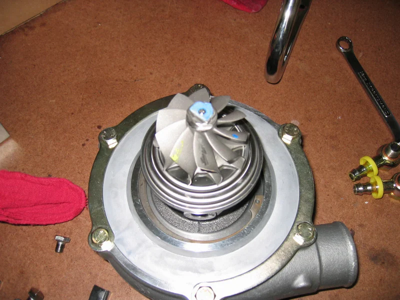 Turbine wheel
Representative turbocharger hardware · reference photo
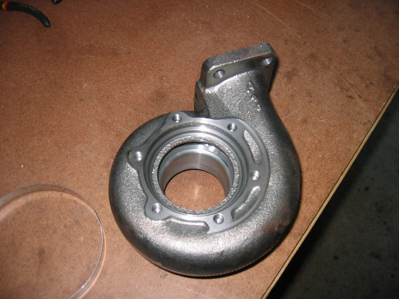 Turbine housing · empty
Representative turbocharger hardware · reference photo
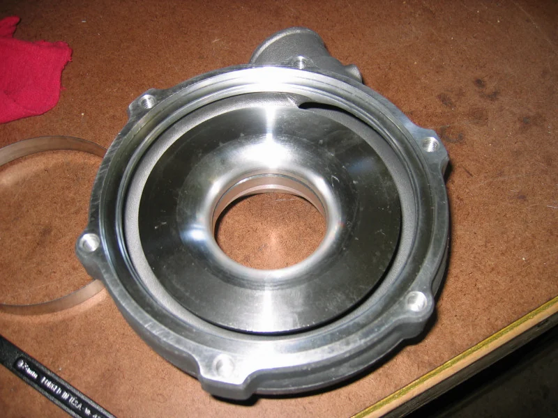 Compressor housing · empty
Representative turbocharger hardware · reference photo
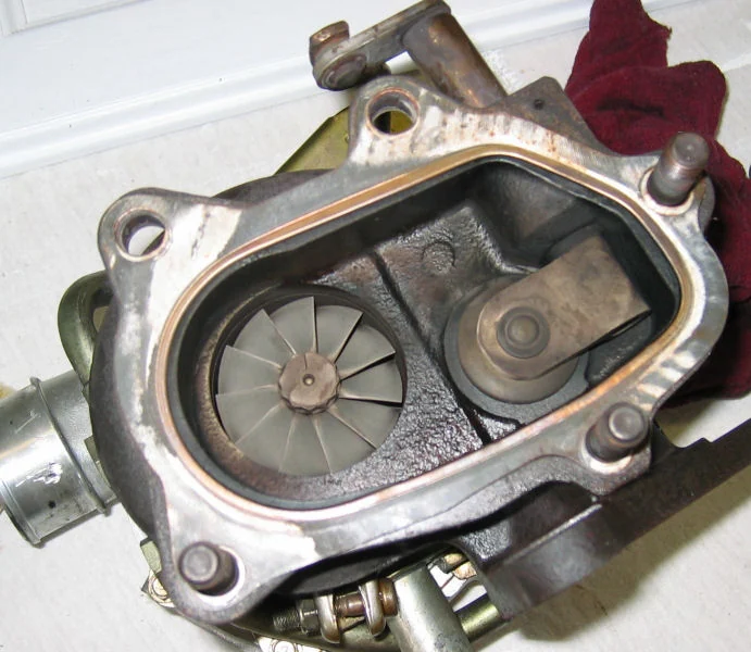 Internal wastegate flapper
CHRA cutaway
What happens inside the center housing
Thrust bearing
Engineering inferenceTakes the fore-aft (axial) load created by the pressure difference across the compressor and turbine wheels. This is the classic N54 hard-boost failure point on stock and lightly-upgraded turbos. Ball-bearing cartridges (Arashi, Tomioka) integrate their own thrust design; FrankenTurbo names a distinct "TD04+ thrust bearing" upgrade. None of it is interchangeable with the OEM journal CHRA's thrust assembly.
TD03 vs TD04 turbine geometry
The clearest, best-documented difference between a TD03 and a TD04L turbine is simply size. Using the factory TD03 turbine (community-measured) against VIV’s own published TD04L dimension:
TD04L turbine vs OEM TD03 — worked from measured and published diameters
Calculated here- Inducer diameter
- +18%
- Inducer disc area
- +39.2%
- Exducer diameter
- +18.1%
- Exducer disc area
- +39.4%
- OEM TD03 wheel trim
- 76.1
- TD04L wheel trim
- 76.2
VIV’s TD04L turbine is about 18% larger in diameter and roughly 39.4% larger in swept disc area than the factory TD03 wheel. But look at the trim: 76.1 for the TD03 versus 76.2 for the TD04L — essentially identical. Unlike the step from TD04L to TD04HL (a genuinely different proportion, covered in the 19T geometry article), a TD04L turbine is essentially a scaled-up copy of the TD03’s shape — the family name changes before the proportions do.
Turbine
The wheel the '19T' badge is silent about
- Inducer (mm)
- Exducer (mm)
True-scale comparison
OEM TD03 vs TD04L turbine wheel, to scale
OEM vs TD04-family CHRA, side by side
The turbine wheel is the easy, well-documented part of this swap. The center section underneath it is where the real architecture change happens — and where most vendors publish the least.
Representative turbocharger hardware · reference photo
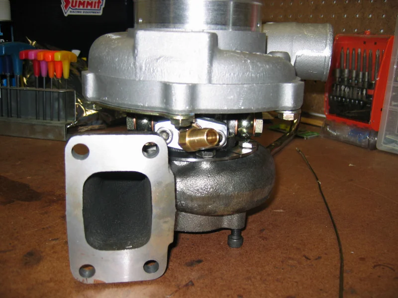 CHRA · assembled
Representative turbocharger hardware · reference photo
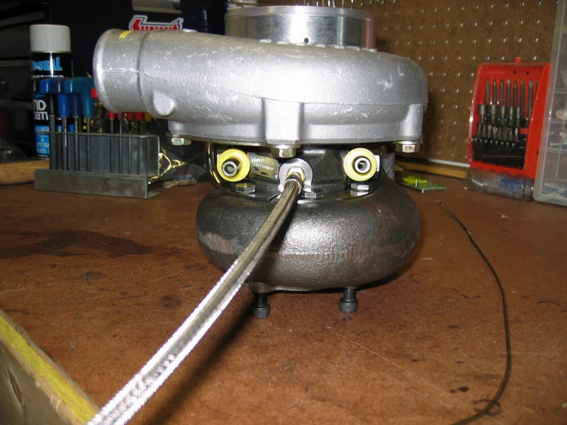 Oil-feed banjo fitting
Center section, side by side
OEM TD03 vs a TD04HL-class ball-bearing CHRA
Thrust bearings and axial load
Boost pushes back on the compressor wheel; exhaust pressure pushes back on the turbine wheel. The net of those two forces is an axial (fore-aft) load on the shaft, and the thrust bearing's entire job is to react it without letting the shaft creep far enough for a wheel to touch its housing. This is widely reported as the single most common failure point on a hard-boosted stock N54 turbo — more common than journal wear, overspeed or housing cracking.
Use the thrust-load mode in the cutaway above, or the simplified calculation here: a first-order estimate of axial force is F = ΔP × A, pressure difference times the wheel's back-disk area. It is not the manufacturer's certified net-thrust figure — that also depends on balance-piston and seal geometry no vendor in this comparison publishes — but it shows why the load scales directly with boost, not with some fixed “25 psi rating.”
Representative turbocharger hardware · reference photo
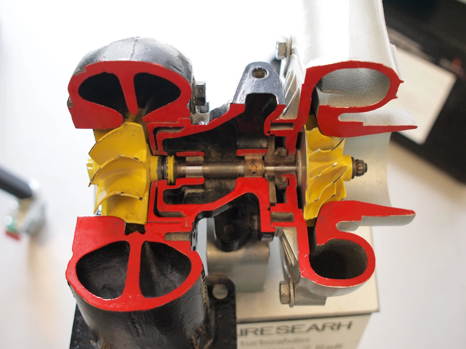 Sectioned shaft & bearings
Thrust wear
Engineering inferenceaxial load risesthrust film thinsshaft creeps fore-aftwheel-to-housing contact
The classic N54 hard-boost failure. As axial load climbs, the thrust bearing's oil film gets thinner before it fails outright — the shaft is allowed a little more fore-aft travel than it should have. Push far enough and the compressor or turbine wheel starts contacting its housing.
Journal wear
Engineering inferenceoil film degradesradial play increaseswheel rubs housing or seal wears
Journal bearings ride on an oil film, not on metal-to-metal contact. Anything that thins or interrupts that film — low pressure, high temperature, contamination, wrong clearance — lets the shaft move more radially than designed, first as noise and shaft play, then as contact.
Heat soak / coking
Engineering inferenceturbine-side heat migrates inoil overheatsoil breaks downvarnish narrows clearance
Heat crosses the shield and the housing metal itself, especially right after a hot shutdown when oil flow stops but the turbine is still radiating heat into the center section. Overheated oil oxidizes and cokes into varnish, which narrows the very clearances the bearings depend on.
Overspeed
Engineering inferenceshaft speed exceeds design limitwheel stress risesblade or hub failure risk
Every wheel has a design shaft-speed ceiling set by material stress at the hub and blade roots. A smaller, lighter wheel can be spun faster before it gets there; a larger wheel reaches its stress limit at a lower shaft speed. This is a wheel property, not a boost-pressure property — see the shaft-speed section below for why.
Drive pressure
Engineering inferenceturbine can't flow enough exhaustbackpressure builds ahead of the wheelcylinder filling and EMP both rise
When the turbine side can't pass exhaust as fast as the engine produces it, pressure builds upstream of the wheel. That raises pumping losses, leaves more hot residual gas in the cylinder, and pushes exhaust manifold pressure up relative to boost — see the EMP:MAP section for the consequences.
Wastegate control
Engineering inferencehousing grows, wastegate port doesn'tflap can't bypass enough exhaustboost creeps past target near redline
Most N54 hybrid and TD04 turbos reuse the factory wastegate flap and actuator. Put that same small port in a bigger turbine housing and, near redline, the flap may not be able to bypass enough exhaust energy to hold boost at target — the turbo keeps making more boost than commanded.
Oil flow, bearings and film
A journal bearing is not lubricated the way a door hinge is — it rides on a pressurized wedge of oil thick enough that the shaft never actually touches the bushing under normal operation. That film depends on three things staying healthy together: adequate feed pressure, a drain that can keep up, and oil that has not overheated past the point of breaking down.
The oil-flow mode in the cutaway above traces the path: one pressurized feed splits to both journal bearings and the thrust bearing, then all of it has to find its way back out through a single gravity drain. That asymmetry is the important part — the feed side is pressurized and can push through a partial restriction, but the drain side cannot. A drain that is even partially blocked backs oil up into the housing long before the feed side shows any symptom, forcing oil past seals it should never reach. This is why more oil pressure is not automatically the fix for a bearing problem: pushing more oil into a system that cannot drain what it already has makes the backup worse, not better.
Bearing clearance interacts with all of this directly. Too tight, and the film can't build enough thickness to stay hydrodynamic under load — metal-to-metal contact follows. Too loose, and the shaft has room to move radially before the film can react, which shows up as audible shaft play and, eventually, wheel-to-housing contact. Neither OEM nor any vendor in this comparison publishes journal clearance figures for the N54, so treat specific clearance numbers you see online as unverified.
TD03 vs TD04 hardware compared
The same real N54 hardware from the 19T geometry article, re-read for center-section specifics. “Not stated” means the vendor does not publish it — that is itself information about how much you can verify before buying.
| Product | CHRA family | Bearing | Journal Ø | Thrust | Power claim | Price | Evidence |
|---|---|---|---|---|---|---|---|
| BMW / Mitsubishi | OEM Mitsubishi TD03 | Journal bearings (plain bushings), oil-film | Not published | Factory single thrust bearing and collar. Community-documented as the first wear point on stock turbos run hard. | ~300–335 hp stock; ~450–500 whp is the practical ceiling on stock frames | — | Independently measured |
| VIV Auto Parts | TD04L-class (per VIV) | Not stated | Not published | Not stated | "up to 775HP" | $1,399 | Unknown |
| Arashi Dynamics | TD04HL-class (per Arashi) | "Dual-row ceramic ball bearing" | Not published | Integrated into the ball-bearing cartridge; no separate thrust-collar dimension is published. | Not stated | $1,937 | Manufacturer-published |
| Tomioka Racing | TD04HL-class (per Tomioka) | "Dual Ceramic Ball Bearing" | Not published | Integrated into the ball-bearing cartridge; not separately published. | "Max Power" listed, figure not published | $3,380 | Manufacturer-published |
| RB Turbo | Custom / full TD04 (per RB) | Not stated | Not published | Not stated | "recommended for 650–700 whp goals" | $3,499 | Unknown |
| FrankenTurbo | "Super-TD04" | "7.5 mm TD04 specification journal bearings" | 7.5 mm | "TD04+ thrust bearing" — named and upgraded from the OEM part. Exact collar width is not published. | "700+ whp capability with excellent low-end responsiveness" | $1,999 | Manufacturer-published |
| PURE Turbos | OEM housings, upgraded CHRA (per PURE) | Not stated (OEM-style CHRA architecture implied) | Not published | Not stated | "650+ WHP Capable"; Daily 450–600 whp / Hi-Flow 600–700 whp | $3,211 | Unknown |
VIV Auto Parts TD04L-class (per VIV)
UnknownSmallest hot side in this group. VIV publishes the turbine and compressor wheel geometry but not the center-section bearing, thrust or oil-port design.
Arashi Dynamics TD04HL-class (per Arashi)
Manufacturer-publishedA ball-bearing cartridge replaces the OEM journal-and-thrust design outright. Arashi does not publish an oil-port or thrust-collar dimension separately from the cartridge.
Tomioka Racing TD04HL-class (per Tomioka)
Manufacturer-publishedSame ball-bearing approach as Arashi. Tomioka publishes its own housing figures in both cm² and inches, which is unusually complete for this group.
RB Turbo Custom / full TD04 (per RB)
UnknownRB publishes the least center-section detail in this group — bearing type, thrust design and oil porting are all unstated.
FrankenTurbo "Super-TD04"
Manufacturer-publishedThe only vendor here that publishes a journal-bearing dimension at all — 7.5 mm, explicitly called "TD04 specification" — plus a named, upgraded thrust bearing.
PURE Turbos OEM housings, upgraded CHRA (per PURE)
UnknownThe center section — not the housings — is PURE's stated upgrade lever, but bearing and thrust specifics for that upgraded CHRA are not published.
Modelled / illustrativeA note on thrust-collar width: some builders describe upgraded N54 CHRAs running a wider collar or spacer — sometimes cited around 14 mm versus a narrower OEM-style part — as one reason they tolerate higher axial load. No vendor above publishes an exact figure, so this article marks it unknown rather than repeating an unsourced number. The cutaway and 3D comparison above draw a wider collar only to illustrate the general pattern, never as a measured dimension.
Failure modes
None of these are scare tactics — they are the mechanical chain from cause to consequence, so you know what a symptom actually means when you see it in a log or on a lift.
Thrust wear
Engineering inferenceaxial load risesthrust film thinsshaft creeps fore-aftwheel-to-housing contact
The classic N54 hard-boost failure. As axial load climbs, the thrust bearing's oil film gets thinner before it fails outright — the shaft is allowed a little more fore-aft travel than it should have. Push far enough and the compressor or turbine wheel starts contacting its housing.
Journal wear
Engineering inferenceoil film degradesradial play increaseswheel rubs housing or seal wears
Journal bearings ride on an oil film, not on metal-to-metal contact. Anything that thins or interrupts that film — low pressure, high temperature, contamination, wrong clearance — lets the shaft move more radially than designed, first as noise and shaft play, then as contact.
Heat soak / coking
Engineering inferenceturbine-side heat migrates inoil overheatsoil breaks downvarnish narrows clearance
Heat crosses the shield and the housing metal itself, especially right after a hot shutdown when oil flow stops but the turbine is still radiating heat into the center section. Overheated oil oxidizes and cokes into varnish, which narrows the very clearances the bearings depend on.
Overspeed
Engineering inferenceshaft speed exceeds design limitwheel stress risesblade or hub failure risk
Every wheel has a design shaft-speed ceiling set by material stress at the hub and blade roots. A smaller, lighter wheel can be spun faster before it gets there; a larger wheel reaches its stress limit at a lower shaft speed. This is a wheel property, not a boost-pressure property — see the shaft-speed section below for why.
Drive pressure
Engineering inferenceturbine can't flow enough exhaustbackpressure builds ahead of the wheelcylinder filling and EMP both rise
When the turbine side can't pass exhaust as fast as the engine produces it, pressure builds upstream of the wheel. That raises pumping losses, leaves more hot residual gas in the cylinder, and pushes exhaust manifold pressure up relative to boost — see the EMP:MAP section for the consequences.
Wastegate control
Engineering inferencehousing grows, wastegate port doesn'tflap can't bypass enough exhaustboost creeps past target near redline
Most N54 hybrid and TD04 turbos reuse the factory wastegate flap and actuator. Put that same small port in a bigger turbine housing and, near redline, the flap may not be able to bypass enough exhaust energy to hold boost at target — the turbo keeps making more boost than commanded.
25 psi is not 25 psi
Here is the calculation that makes this article's title true. Twenty-five psi of boost is a pressure ratio of about 2.7:1 — full stop, regardless of RPM. What is not fixed is how much air the engine needs moved to hold that ratio, and that scales almost directly with RPM:
25 psi is not 25 psi
Same 25 psi, three engine speeds — mass flow triples
Going from 3,000 to 5,000 to 7,000 rpm at the same 25 psi target means moving about 26.6 lb/min of air, then 44.3 lb/min, then 62 lb/min — roughly 2.3× more from bottom to top of that range. More intake mass flow means more exhaust mass flow behind it, which means the turbine has to do more work to hold the same pressure ratio. That additional work has to come from somewhere: higher shaft speed, higher drive pressure, or both.
Shaft speed demand
Holding one pressure ratio costs more shaft speed as RPM rises
A boost number without RPM, airflow and turbine-side conditions tells you very little about actual turbo stress. Two cars logging an identical 25 psi peak can be putting completely different loads on their thrust bearings, journals and oil film, depending entirely on where in the RPM range that boost is held.
Pressure ratio, explained
This is the most commonly misunderstood number in turbo tuning. A boost gauge reads gauge pressure — pressure above atmosphere. A compressor's actual job is described by pressure ratio: absolute outlet pressure over absolute inlet pressure, atmosphere included on both sides.
Pressure ratio
25 psi gauge boost is not a 25:1 pressure ratio
14.7 psi absolute — the number most boost gauges are calibrated against.
Pressure ratio
2.7 : 1
(39.7 ÷ 14.7 psi absolute)
At standard sea-level atmosphere (14.696 psi absolute), 25 psi of boost is a pressure ratio of 2.7:1 — not 25:1, and not even close. That distinction matters because compressor maps, efficiency and choke limits are all plotted against pressure ratio, not gauge boost. Two cars in different climates or altitudes chasing the same boost number are actually asking their compressors for slightly different pressure ratios.
Drive pressure and EMP : MAP
Boost is only half the pressure story. On the other side of the engine, exhaust manifold pressure (EMP) — the pressure the engine has to push against to exhale — can matter just as much as intake manifold pressure (MAP) for how hard a turbo, and the engine behind it, is working.
1 : 1
Engineering inferenceEMP roughly equal to MAP. Comfortable — the engine is not fighting its own exhaust to breathe in.
1.5 : 1
Engineering inferenceA commonly cited zone where pumping losses and residual exhaust start becoming noticeable on data logs.
2 : 1
Engineering inferenceMeaningful pumping work. Cylinder filling and exhaust temperature both start moving in the wrong direction.
2.5 : 1+
Engineering inferenceA small, restrictive turbine relative to demand. No universal failure threshold exists — treat this as a warning zone, not a cliff edge.
As EMP rises relative to MAP: pumping losses increase, more hot residual exhaust stays trapped in the cylinder instead of being scavenged, exhaust gas temperature climbs, thrust load on the turbine wheel increases, and the engine has to work harder just to maintain the boost target it already reached. None of the specific ratio thresholds above are universal cutoffs — they are a general shape, not a certified limit, and no Synergy EMP-instrumented log exists in this article's sourcing to turn them into measured figures. If you have logged EMP against MAP on an N54 and want it considered for a future update, send it our way.
How to compare before buying
Get these in writing from any center-section vendor before you buy:
- Bearing type — journal or ball — and, if journal, the diameter if they'll state it.
- Thrust bearing design and whether it's a named upgrade or the OEM-pattern part in a new housing.
- Oil-port configuration: feed and drain sizing, and whether the OEM drain is reused unmodified.
- Turbine wheel inducer and exducer diameter, and its heat-shield height if changing turbine families.
- Turbine housing size, and whether it's quoted in A/R or cm², and by whom.
- What RPM range and boost level the power claim was actually made at.
- Whether independent EMP or drive-pressure data exists for the specific product, not just a dyno number.
A “TD04” badge is a starting point for that conversation, not the end of it — see the 19T geometry article for the same lesson applied to compressor sizing. If you want a second set of eyes on a specific turbo against a specific power and RPM goal, that's what a build consult is for.
FAQ
- What actually changes between a TD03 and a TD04 center section on an N54?
- The turbine wheel gets bigger first — VIV's TD04L is about 47.2 mm inducer versus the factory TD03's 40 mm, roughly 18% larger in diameter and about 39.2% larger in swept area. From there it depends entirely on the vendor: some keep OEM-style journal bearings and a factory-pattern thrust assembly, others move to a dual ceramic ball-bearing cartridge with its own thrust design. Housing size, blade count and wastegate setup all move independently of the "TD03 vs TD04" label. There is no single answer that covers every product sold under either name.
- Does a TD04 CHRA really handle more boost than a TD03?
- It can, but not because '25 psi' is a fixed load a bigger part simply shrugs off. A larger turbine wheel and housing pass a given exhaust mass flow at lower drive pressure, which lowers thermal and pressure loading on the bearings and thrust assembly at the same RPM and airflow. The honest version is: a TD04 center section generally has more margin before the failure modes below start, not that a specific PSI number becomes automatically survivable.
- Journal bearing or ball bearing — which should I run?
- Neither is strictly 'better'; they fail differently. Ball-bearing cartridges (Arashi, Tomioka) spool marginally sooner and tolerate brief low-oil-pressure moments better, since they don't depend entirely on a continuous hydrodynamic film. Journal bearings (OEM, FrankenTurbo) are cheaper, quieter, and perfectly durable for a long service life when oil supply and drain are both healthy — the OEM design's real weak point historically has been the thrust assembly, not the journals themselves.
- Why do two turbos both boosting 25 psi behave so differently?
- Because 25 psi only fixes the pressure ratio — about 2.7:1 at sea level, at any RPM. It does not fix the mass flow the turbo has to move to get there. Holding that same 25 psi at 3,000 rpm versus 7,000 rpm on an N54 means moving roughly 26.6 lb/min of air versus 62 lb/min — nearly 2.3× more — which means more exhaust energy, more shaft speed, more thrust load and more heat, all behind an identical boost-gauge reading. See the "25 psi is not 25 psi" section for the full calculation.
- What actually fails first on a hard-boosted stock N54 turbo?
- The thrust bearing, by wide community consensus. It reacts the axial load created by the pressure difference across the compressor and turbine wheels, and the factory single thrust assembly has the least margin of anything in the center section. Journal wear, heat soak and wastegate control issues all matter, but thrust failure is the one that ends a stock turbo's life on a sustained high-boost tune.
- Does more oil pressure fix a turbo bearing problem?
- Not by itself. Bearings need adequate feed pressure, but they also need a clear, unrestricted drain — a partially blocked or kinked drain line backs oil up into the center housing faster than raising feed pressure can push it through, and forces oil past seals it should never reach. More pressure into a system that can't drain what it already has makes the problem worse, not better.
- What is EMP and why does it matter as much as boost?
- EMP is exhaust manifold pressure — the pressure the engine has to push against to expel exhaust gas, upstream of the turbine wheel. When EMP rises relative to intake manifold pressure (MAP), pumping losses increase, more hot residual gas stays in the cylinder, exhaust temperatures climb, and the turbine sees more thrust load holding the same boost. A turbo that controls boost fine can still be under far more stress than one making identical boost with lower EMP.
- How do I know if a 'TD04' CHRA is actually upgraded, not just relabeled?
- Ask for the specifics in writing: bearing type (journal or ball), journal or thrust dimensions if published, oil-port configuration, turbine wheel inducer/exducer and blade count, and housing size in A/R or cm². Very few vendors in this comparison publish all of it — FrankenTurbo is the only one that states a journal-bearing dimension at all. A frame name alone tells you almost nothing about what's actually inside.
Evidence and method
Every non-obvious number on this page is tagged with where it comes from:
- Manufacturer-published
- Stated by the part maker on the product page or spec sheet.
- Independently measured
- Measured off physical wheels and catalogued by the turbo community; cross-checked across independent listings.
- Calculated here
- Worked out on this page from the measured or manufacturer dimensions, with the formula shown.
- Modelled / illustrative
- A drawn approximation to make the geometry legible. Not a measurement and not a performance claim.
- Engineering inference
- What the physics leads us to expect. Directionally sound; the exact number is not established.
- Unknown
- No figure we are willing to publish. The manufacturer does not state it and it has not been measured.
What is solid, and what is not
- Solid: the factory TD03 turbine measures ~40 / 34.9 mm; VIV publishes its TD04L turbine at 47.2 / 41.2 mm; pressure ratio from gauge boost is exact arithmetic; the mass-flow-scales-with-RPM relationship is calculated from the ideal gas law, not asserted; FrankenTurbo is the only vendor here publishing a journal-bearing dimension (7.5 mm); Arashi's and VIV's own published heat-shield heights (13 mm vs 5 mm) are real and sourced.
- Unresolved: thrust-collar width for every vendor in this comparison, including the ~14 mm figure sometimes cited for upgraded parts; journal bearing diameter for everyone except FrankenTurbo; oil-port configuration for every vendor; exact EMP:MAP thresholds for real failure risk on the N54 specifically; whether a general OEM-vs-upgrade thrust bearing life multiplier can be stated numerically.
- Not claimed: no specific PSI is asserted as a survivable or unsurvivable threshold for any turbo here. The shaft-speed-demand curve and the axial-thrust calculation are both labelled illustrative or simplified — neither is a manufacturer's certified figure. No EMP datalog is presented as measured; the EMP:MAP ratios are a conceptual ladder, not a threshold table. The real photographs on this page (Garrett GT30 and IHI VF39 hardware, Wikimedia Commons, credited in place) are reference photos of the same kind of part, included for scale and orientation — none of them is the specific N54 TD03/TD04 unit, and no N54-specific photography of internal bearings, shafts or thrust hardware exists in this article's sourcing. Those geometry figures stay clearly labelled illustrations instead of a photograph standing in for one.
Sources
- VIV Auto Parts
- Arashi Dynamics
- Tomioka Racing
- RB Turbo
- FrankenTurbo
- PURE Turbos
- Arashi Dynamics — heat shields for TD04-series turbine wheels
- Arashi Dynamics — MHI / Mitsubishi turbo wheel sizes
Reviewed by Justin, Owner & BMW Calibration Specialist at Synergy BMW Tuning. Updated September 2026. Found an error or have a measured dimension to add? Tell us and we will correct it.
Building past what a stock center section can take?
Tell us your power target, RPM range and fuel and we will tell you which center section and bearing system actually fit the goal — before you buy.
Start a build consult →- You Think a 19T Is a 19T? N54 TD04L vs TD04HL'19T' names a compressor wheel, not a turbo. TD04L vs TD04HL turbine geometry, calculated, against real VIV, Arashi, Tomioka, RB, FrankenTurbo and PURE N54 hardware.
- BMW N54 Head Flow: Stock vs Ported vs N53 SwapSuperFlow SF-600 data comparing the stock N54 head, a mild ported N54 and a mild ported N53 head—plus port measurements and cam/lift takeaways for 500–700+ whp builds.
- The Science of Flow: Why N54 Calibration Is Mandatory After Head PortingPorting an N54 head (or swapping to an N53 head) changes VE, load and torque prediction. Here’s why a full recalibration is mandatory for safe fueling, timing and boost control.
- N54 Single Turbo Checklist: What to Sort Before Your TuneA practical N54 single turbo checklist covering fueling, boost control, sensors, and logging prep so your remote tuning process starts clean.
- BMW N54 TuningIconic twin-turbo BMW platform. Supports stock twins through big singles with full fuel/boost/timing optimization and strong safety strategy.
- B58 vs N54 Tune Guide | Power, Reliability, and Upgrade PathsCompare BMW B58 vs N54 tuning potential, fueling, spool, reliability, and supporting mods for daily-driven and big-power builds.
- N54 vs N55 Tune Guide | Which BMW Inline-6 Is Better to Tune?Compare N54 and N55 tuning potential, spool, fueling limits, reliability, and common upgrade paths.
- How to Read a BMW DatalogA channel-by-channel guide: boost vs target, wastegate duty, timing correction, fueling, rail pressure, IAT and load limits, with worked examples.