B58 Gen 2 — Calibration Case Study
B58 Gen 2 RF Codes Above 30 PSI: What We Found and How We Addressed Them
B58 Gen 2 RF Codes During High-Boost Tuning
On this customer's B58 Gen 2 BMW, high-boost tuning presented two problems that needed separate attention: RF activity near the top of the pull, and boost control that moved between overshoot, under-target operation and oscillation. Increasing the boost target alone would not address either the injection-window concern or the way wastegate duty was responding.
Our calibration work covered the single-pulse end-of-injection angle and the wastegate base, proportional and derivative settings. The logs show why both areas needed attention. In one early fourth-gear window, MHD+ boost reached 32.56–36.02 PSI against a 27.9 PSI RAM target. Later, the selected boost-control comparison improved from a 1.45 PSI mean shortfall to 0.66 PSI, with less variation in wastegate duty.
The RF behavior required its own evaluation. RF2, RF6 and RF8 appeared under different conditions, including pressures on both sides of 30 PSI. That pressure describes the operating range of this project; it is not a universal B58 fault threshold.
Understanding the RF Behavior
The relevant MHD channel is RF Max Index (-). It provides a recorded index that can be compared with RPM, boost, load and fuel-pressure behavior. It is not a diagnostic scan, and the available records do not establish exact BMW DTC mappings for RF2, RF6 or RF8. We therefore evaluated each index alongside the operating conditions instead of assigning all three the same cause.
| RF index | Observed behavior in this project |
|---|---|
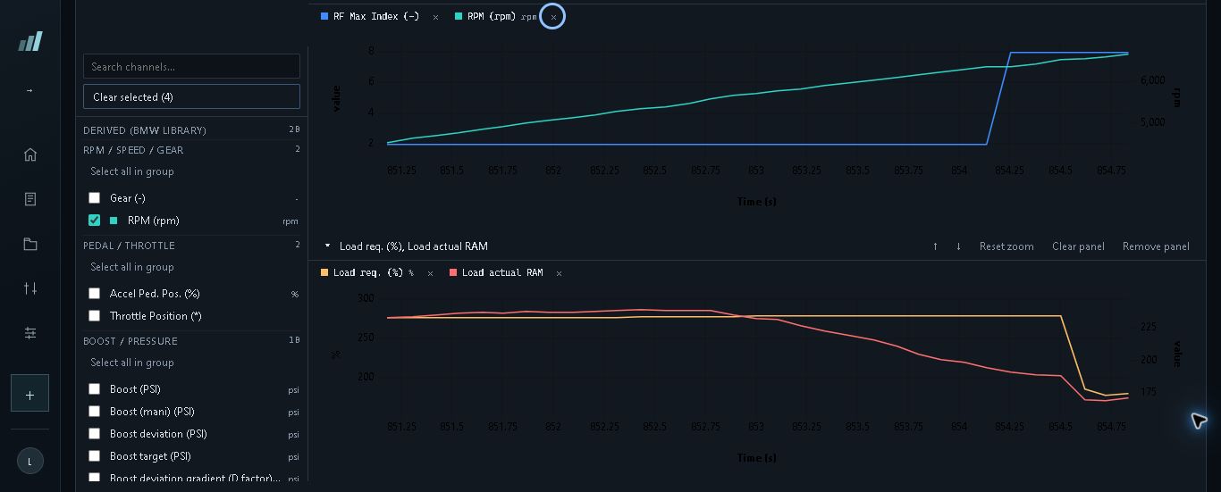
| RF2 | Index two was present at lower boost and through the early 32.56–36.02 PSI MHD+ overboost window. Crossing 30 PSI did not mark its first appearance. |
| RF6 | A separate log recorded index six at low pressure and with standard boost reaching 34.3 PSI. Its presence was not limited to high boost. |
| RF8 | Index eight appeared near the upper end of fourth-gear pulls. Two recorded transitions occurred at 6,222 RPM and 6,356 RPM. |
At the 6,222 RPM transition, MHD+ boost was 30.17 PSI. At the 6,356 RPM transition, standard boost was 29.6 PSI; that export did not contain MHD+ boost. Keeping those channel names attached to the readings avoids treating two different exported signals as interchangeable measurements.
The upper-RPM location was particularly useful. A comparison ending at 6,000 RPM could show improved boost tracking while completely missing the later index-eight transition. Requested load also fell later in one index-eight interval. That gave us a load response to examine, although load and torque readback alone did not identify the active limiter.
How Synergy Approached the Calibration
We considered the boost-control problem and the RF/fuel-performance concern separately, then checked how they appeared together in the logs. That meant comparing requested and actual boost, wastegate duty, RPM, gear, pedal, throttle, load and rail pressure, with mixture and timing channels where available.
The first requirement was to use the correct boost target. In the earlier selected comparison window, the standard target was 22.9 PSI while Boost target RAM (PSI) was 29.9 PSI. Comparing actual boost with the lower standard target would make the same pull look very different. For the numerical comparison here, we use MHD+ Boost (PSI) against Boost target RAM (PSI), retaining their exported units.
The selected windows share fourth gear, pedal of at least 95%, a 4,500–6,000 RPM band and a constant 29.9 PSI RAM target. We did not filter out throttle movement to make the tracking result look cleaner. The separate RF review extends through the upper-RPM portion of the pulls.
Rail pressure helped narrow the fuel-performance question. At the two index-eight transitions, actual and requested pressures were:
| RF transition | Rail pressure actual | Rail pressure requested |
|---|---|---|
| 6,222 RPM | 5,038.3 PSI | 5,076.3 PSI |
| 6,356 RPM | 5,177.9 PSI | 5,076.3 PSI |
Neither sample shows a rail-pressure collapse. That made it necessary to consider the injection timing requirement separately rather than treating pressure readback as a complete explanation of the RF behavior. Pressure following request does not establish that injection is finishing within the required window.
Injection Timing and Boost-Control Adjustments
The injection-angle work addressed Latest End of Injection Angle (Single Pulse). This concerns the timing requirement for completing single-pulse injection. We adjusted that calibration as part of the fuel-performance and injection-window work, rather than assuming that a satisfactory rail-pressure trace settled the issue.
The wastegate work addressed the overshoot and oscillation. We first adjusted base duty and set the D contribution to zero while establishing the base, with P control retained. This gave the base-duty work a defined starting point before further changes to the feedback settings. We also reduced duty during lift-off as part of the boost-control corrections.
For the oscillation, we subsequently reduced P, added D and lowered base duty. The purpose was to smooth the response while bringing actual boost closer to request. The intermediate result showed why both needed checking: the duty command became steadier, but boost fell further below target. A smooth WGDC trace by itself was not a successful calibration result.
The later comparison showed a narrower duty range together with better boost tracking. We evaluated that relationship rather than judging the adjustment from a single channel. The base/P/D work was directed at boost control; the records do not establish that those changes directly repaired RF faults. Injection-angle work and wastegate refinement addressed different parts of the problem.
Results From the Datalogs
The selected fourth-gear comparison shows the progression from a fluctuating duty command to closer boost tracking. Mean shortfall is calculated as RAM target minus MHD+ actual boost, averaged across each window's original samples without smoothing or interpolation.
| Selected test window | Samples | Mean boost shortfall | Logged WGDC range |
|---|---|---|---|
| Earlier boost-control test | 22 | 1.45 PSI | 89.3–100.0% |
| Intermediate damping test | 21 | 2.82 PSI | 90.3–91.7% |
| Later boost-control test | 19 | 0.66 PSI | 89.4–92.0% |
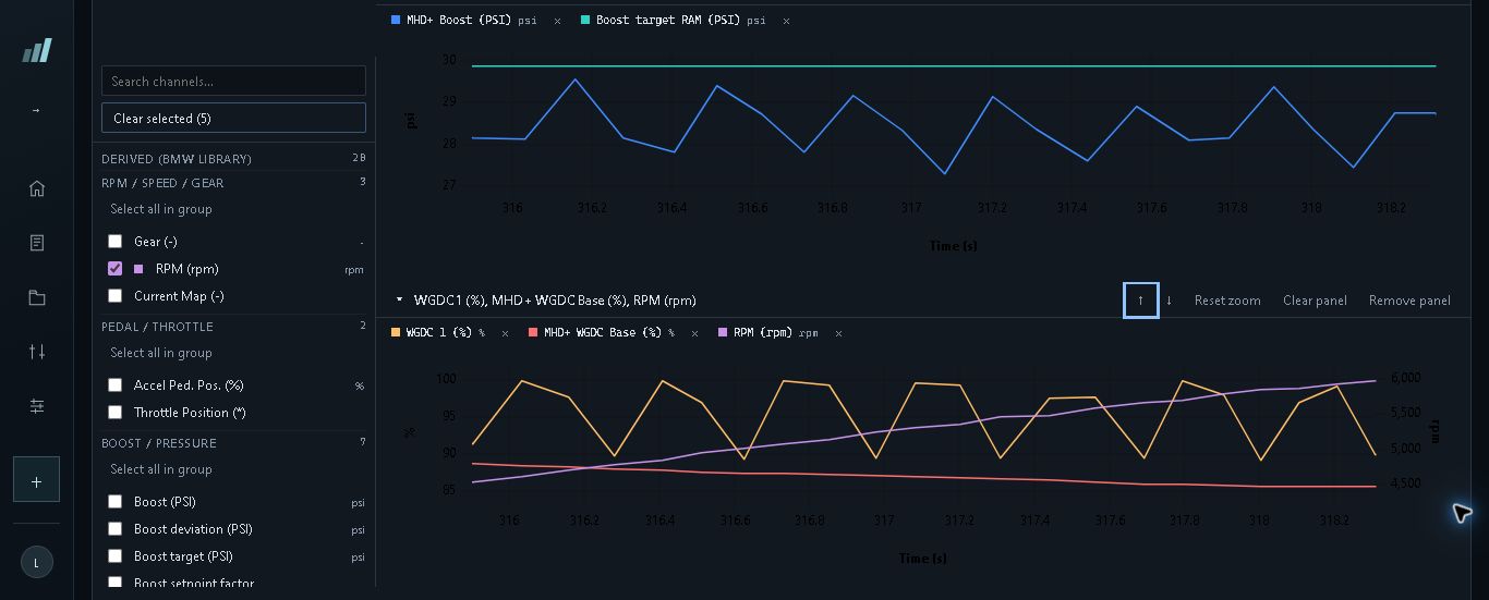
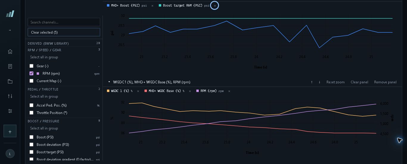
The later window has both a smaller average deficit and less duty variation than the earlier one. The improvement from 1.45 PSI to 0.66 PSI mean shortfall is a measured result across the selected tests. Intake temperatures also changed from 66–75 °F to 57–66 °F, while fuel composition, adaptations and intervening changes were not held constant. This comparison shows the progression in tracking, without isolating one adjustment as its sole cause.
RF behavior still needed to be checked beyond the boost-comparison window. A separate later log records RF index zero throughout all 115 records, including a full-pedal fourth-gear pull to 6,589 RPM. MHD+ boost reaches 30.34 PSI during that pull.
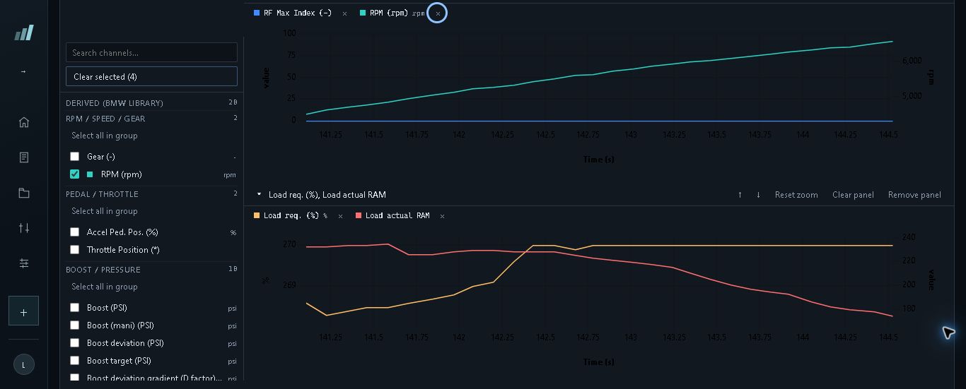
That establishes a zero-RF operating interval beyond the RPM where index eight appeared in the earlier examples. It does not identify which calibration change produced that interval, so we do not attribute it to our injection-angle or WGDC adjustments. Requested load differed, and cylinder-six correction reached −3.0 in the export's native units at upper RPM.
Subsequent testing still included an index-eight sample during a shift and recurring boost-repeatability concerns. The demonstrated results are improved boost tracking and a specific zero-RF interval; permanent RF elimination and a definitive root-cause repair are not established.
Why Proper Custom Calibration Matters
This B58 required attention to more than the requested boost number. The standard and RAM targets differed, wastegate duty could become steadier while tracking worsened, and the RF transition occurred above the RPM band used for the boost comparison. Each of those details changes how a tuner should interpret the pull.
Our work addressed the injection timing requirement and refined wastegate base/P/D behavior, with the logs used to evaluate the response. The relevant standard is whether the calibration produces the intended behavior across the operating range: boost following request, appropriate control response and RF behavior checked where the problem occurs. Repeat logs are needed when adaptation state or driving conditions change the result.
That is the approach behind our custom B58 calibration work: review the vehicle's setup, identify the relevant control behavior, make targeted adjustments and check the next log against the original problem. Our BMW datalogging guide explains how to capture the channels and operating conditions needed for that review.
Pick your platform, select your hardware stage, add what you need, and checkout to start intake immediately.
Get a Quote →